Appointment
2.4.1. Voltage indicators are designed to determine the presence or absence of voltage on live parts of electrical installations.
2.4.2. The general technical requirements for voltage indicators are set out in the national standard.
Voltage indicators above 1000 V
Principle of operation and design
2.4.3. Voltage indicators above 1000 V react to a capacitive current flowing through the indicator when its working part is introduced into an electric field formed by live parts of electrical installations that are energized and "ground" and grounded structures of electrical installations.
2.4.4. Indicators should contain the main parts: working, indicator, insulating, as well as a handle.
2.4.5. The working part contains elements that react to the presence of voltage on the monitored live parts.
Housings of working parts of voltage indicators up to 20 kV inclusive must be made of insulating materials with stable dielectric characteristics. Cases of working parts of voltage indicators 35 kV and above can be made of metal.
The working part may contain a tip electrode for direct contact with the monitored live parts and not contain a tip electrode (non-contact type indicators).
The indicator part, which can be combined with the working part, contains elements of light or combined (light and sound) indication. Gas-discharge lamps, LEDs or other indicators can be used as light indication elements. Light and sound signals must be reliably recognizable. The audio signal should have a frequency of 1 - 4 kHz and an interruption frequency of 2 - 4 Hz when indicating the phase voltage. The sound signal level must be at least 70 dB at a distance of 1 m along the axis of the sound radiator.
The working part may also contain a body for its own health control. Monitoring can be carried out by pressing a button or be automatic, by periodically giving special control signals. At the same time, it should be possible to fully check the health of the electrical circuits of the working and indicator parts.
Working parts should not contain switching elements designed to turn on power or switch ranges.
2.4.6. The insulating part of the indicators must be made of the materials specified in clause 2.1.2.
The insulating part can be composed of several links. To connect the links to each other, parts made of metal or insulating material can be used. The use of a telescopic structure is allowed, while spontaneous folding should be excluded.
2.4.7. The handle can be integral with the insulating part or be a separate link.
2.4.8. The design and weight of the signs should ensure that one person can work with them.
2.4.9. The electrical circuit and design of the pointer must ensure its operability without grounding the working part of the pointer, including when checking the absence of voltage, carried out from telescopic towers or from wooden and reinforced concrete supports of 6-10 kV overhead lines.
2.4.10. The minimum dimensions of insulating parts and handles for voltage indicators above 1000 V are given in table. 2.4.
Table 2.4
MINIMUM DIMENSIONS OF INSULATING PARTS AND HANDLES FOR VOLTAGE INDICATORS ABOVE 1000 V
2.4.11. The indication voltage of the voltage indicator should be no more than 25% of the rated voltage of the electrical installation.
For indicators without a built-in power supply with a pulse signal, the indication voltage is the voltage at which the signal interruption frequency is at least 0.7 Hz.
For indicators with a built-in power supply with a pulse signal, the indication voltage is the voltage at which the signal interruption frequency is at least 1 Hz.
For other indicators, the indication voltage is the voltage at which there are distinct light (light and sound) signals.
2.4.12. The time of appearance of the first signal after touching a live part under voltage equal to 90% of the nominal phase voltage should not exceed 1.5 s.
2.4.13. The working part of the pointer for a certain voltage should not react to the influence of neighboring circuits of the same voltage, spaced from the working part at the distances indicated in table. 2.5.
Table 2.5
DISTANCE TO NEAREST MIDDLE CIRCUIT WIRE

Performance Tests
2.4.14. During operation, mechanical tests of voltage indicators are not carried out.
2.4.15. Electrical tests of voltage indicators consist of overvoltage tests of the insulating part and determination of the indication voltage.
Testing of the working part of voltage indicators up to 35 kV is carried out for indicators of such a design, during operations with which the working part can cause a phase-to-phase short circuit or a phase-to-earth short circuit. The need for testing the insulation of the working part is determined by the operating manuals.
For voltage indicators with a built-in power supply, its condition is monitored and, if necessary, the batteries are recharged or the batteries are replaced.
2.4.16. When testing the insulation of the working part, the voltage is applied between the tip electrode and the screw connector. If the pointer does not have a screw connector electrically connected to the indication elements, then the auxiliary electrode for connecting the test device wire is installed at the border of the working part.
2.4.17. When testing the insulating part, the voltage is applied between the element of its articulation with the working part (threaded element, connector, etc.) and a temporary electrode applied to the restraining ring from the side of the insulating part.
2.4.18. The indication voltage of indicators with a gas-discharge indicator lamp is determined according to the same scheme according to which the insulation of the working part is tested (clause 2.4.16).
When determining the indication voltage of other indicators having a tip electrode, it is connected to the high-voltage terminal of the test setup. When determining the indication voltage of indicators without a tip electrode, it is necessary to touch the end side of the working part (head) of the indicator to the high-voltage terminal of the test setup.
In both latter cases, the auxiliary electrode is not installed on the indicator and the ground terminal of the test setup is not connected.
The voltage of the test setup rises smoothly from zero to the value at which the light signals begin to comply with the requirements of clause 2.4.11.
2.4.19. The norms and frequency of electrical tests of indicators are given in Appendix 7.
Terms of use
2.4.20. Before starting work with the pointer, it is necessary to check its serviceability.
The serviceability of indicators that do not have a built-in control body is checked using special devices, which are small-sized sources of increased voltage, or by briefly touching the indicator tip electrode to live parts that are obviously energized.
The serviceability of indicators with a built-in control unit is checked in accordance with the operating manuals.
2.4.21. When checking the absence of voltage, the time of direct contact of the working part of the indicator with the monitored current-carrying part must be at least 5 s (in the absence of a signal).
It should be remembered that, although some types of voltage indicators can give a signal about the presence of voltage at a distance from live parts, direct contact with the working part of the indicator is mandatory.
2.4.22. In electrical installations with voltages above 1000 V, use the voltage indicator with dielectric gloves.
Voltage indicators up to 1000 V
Purpose, principle of operation and design
2.4.23. General technical requirements for voltage indicators up to 1000 V are set out in the state standard.
2.4.24. In electrical installations with voltage up to 1000 V, two types of indicators are used: two-pole and single-pole.
Two-pole indicators operating with active current flow are intended for AC and DC electrical installations.
Single-pole indicators operating with a capacitive current flow are intended for electrical installations only with alternating current.
The use of two-pole pointers is preferred.
The use of test lamps for checking the absence of voltage is not allowed.
2.4.25. Two-pole indicators consist of two cases made of electrical insulating material, containing elements that react to the presence of voltage on the monitored live parts, and elements of light and (or) sound indication. The housings are interconnected by a flexible wire with a length of at least 1 m. At the points of entry into the housings, the connecting wire must have shock-absorbing bushings or thickened insulation.
The dimensions of the enclosures are not standardized, they are determined by the ease of use.
Each case of a two-pole indicator must have a rigidly fixed electrode tip, the length of the uninsulated part of which should not exceed 7 mm, except for indicators for overhead lines, in which the length of the uninsulated part of the electrode tips is determined by the specifications.
2.4.26. The single-pole indicator has one housing made of electrically insulating material, in which all the elements of the indicator are located. In addition to the tip electrode that meets the requirements of clause 2.4.25, there must be an electrode on the end or side of the body for contact with the operator's hand.
The dimensions of the case are not standardized, they are determined by the ease of use.
Voltage presence indication can be stepped, supplied as a digital signal, etc.
Light and sound signals can be continuous or intermittent and must be reliably recognizable.
For indicators with a pulse signal, the indication voltage is the voltage at which the interval between pulses does not exceed 1.0 s.
2.4.28. Voltage indicators up to 1000 V can also perform additional functions: checking the continuity of electrical circuits, determining the phase conductor, determining the polarity in DC circuits, etc. In this case, the indicators should not contain switching elements intended for switching operating modes.
Expanding the functionality of the indicator should not reduce the safety of operations to determine the presence or absence of voltage.
Performance Tests
2.4.29. Electrical tests of voltage indicators up to 1000 V consist of insulation testing, determination of the indication voltage, checking the operation of the indicator at an increased test voltage, checking the current flowing through the indicator at the highest operating voltage of the indicator.
If necessary, the indication voltage in the DC circuits is also checked, as well as the correctness of the polarity indication.
The voltage gradually increases from zero, while the values of the indication voltage and the current flowing through the pointer at the maximum operating voltage of the pointer are recorded, after which the pointer is held for 1 min. withstands at an increased test voltage exceeding the maximum operating voltage of the indicator by 10%.
2.4.30. When testing pointers (except for insulation testing), the voltage from the test setup is applied between the tip electrodes (for two-pole indicators) or between the tip electrode and the electrode on the end or side of the case (for single-pole indicators).

Fig. 2.1. Schematic diagram of testing the dielectric strength of the insulation of the handles and the voltage indicator wire:
1 - test pointer; 2 - test transformer; 3 - bath with water; 4 - electrode
2.4.31. When testing the insulation of two-pole indicators, both housings are wrapped in foil, and the connecting wire is lowered into a vessel with water at a temperature of (25 +/- 15) ° C so that the water covers the wire, 8-12 mm away from the handles of the housings. One wire from the test setup is connected to the tip electrodes, the second, grounded, to the foil and lowered into water (a variant of the circuit - Fig. 2.1).
For single-pole indicators, the body is wrapped in foil along the entire length up to the limit stop. A gap of at least 10 mm is left between the foil and the contact on the end (side) part of the case. One wire from the test rig is connected to the tip electrode, the other to the foil.
Appointment
1. Voltage indicators are designed to determine the presence or absence of voltage on live parts of electrical installations.
2. General technical requirements for voltage indicators are set out in the national standard.
Voltage indicators above 1000V
Principle of operation and design
3. Pointers of voltage higher than 1000 V react to the capacitive current flowing through the pointer when its working part is introduced into the electric field formed by live parts of electrical installations that are energized and "ground" and grounded structures of electrical installations.
4. Pointers should contain the main parts: working, indicator, insulating, as well as a handle.
5. Working part contains elements that react to the presence of voltage on the monitored live parts.
The working part may contain a tip electrode for direct contact with the monitored live parts and not contain a tip electrode (non-contact type indicators).
Indicator part, which can be combined with the working one, contains elements of light or combined (light and sound) indication. Light and sound signals must be reliably recognizable.
The working part may also contain a body for its own health control. Monitoring can be carried out by pressing a button or be automatic, by periodically giving special control signals.
6. The insulating part can be composed of several links. To connect the links to each other, parts made of metal or insulating material can be used. The use of a telescopic structure is allowed, while spontaneous folding should be excluded.
7. The handle can be integral with the insulating part or be a separate link.
8. The design and weight of the signs should ensure the ability to work with them by one person.
9. The electrical circuit and design of the pointer must ensure its operability without grounding the working part of the pointer, including when checking the absence of voltage, carried out from telescopic towers or from wooden and reinforced concrete poles of 6-10 kV overhead lines.
10. The indication voltage of the voltage indicator should be no more than 25% of the rated voltage of the electrical installation.
11. The time of appearance of the first signal after touching a live part, which is under voltage equal to 90% of the nominal phase voltage, should not exceed 1.5 s.
12. The working part of the pointer for a certain voltage should not react to the influence of adjacent circuits of the same voltage.
Performance Tests
13. During operation, mechanical tests of voltage indicators are not carried out.
14. Electrical tests of voltage indicators consist of overvoltage testing of the insulating part and determination of the indication voltage.
For voltage indicators with a built-in power supply, its condition is monitored and, if necessary, the batteries are recharged or the batteries are replaced.
15. When testing the insulation of the working part, the voltage is applied between the tip electrode and the screw connector or at the boundary of the working part.
16. When testing the insulating part, the voltage is applied between the element of its articulation with the working part (threaded element, connector, etc.) and a temporary electrode applied to the restraining ring from the side of the insulating part.
17. The indication voltage of the pointers is checked as follows - the voltage of the test setup rises smoothly from zero to the value at which the light signals begin to correspond to 25%.
18. Norms and frequency of electrical tests of pointers are given in the table.
Terms of use
19. Before starting work with the pointer, it is necessary to check its serviceability.
The serviceability of indicators that do not have a built-in control body is checked using special devices, which are small-sized sources of increased voltage, or by briefly touching the indicator tip electrode to live parts that are obviously energized.
20. When checking the absence of voltage, the time of direct contact of the working part of the indicator with the monitored current-carrying part must be at least 5 s (in the absence of a signal).
It should be remembered that although some types of voltage indicators may signal the presence of voltage at a distance from live parts, direct contact with them the working part of the pointer is mandatory.
21. In electrical installations with voltages above 1000V, use the voltage indicator with dielectric gloves.
Voltage indicators up to 1000V
Purpose, principle of operation and design
22. In electrical installations with voltage up to 1000V, two types of indicators are used: two-pole and single-pole.
Two-pole indicators operating with active current flow are intended for AC and DC electrical installations.
Single-pole pointers operating with the flow of capacitive current are intended for electrical installations AC only.
The use of two-pole pointers is preferred.
The use of test lamps for checking the absence of voltage is not allowed.
23. Two-pole indicators consist of two cases made of electrical insulating material, containing elements that react to the presence of voltage on the monitored live parts, and elements of light and (or) sound indication. The housings are interconnected by a flexible wire with a length of at least 1 m. At the points of entry into the housings, the connecting wire must have shock-absorbing bushings or thickened insulation.
The dimensions of the enclosures are not standardized, they are determined by the ease of use.
Each case of a two-pole indicator must have a rigidly fixed electrode tip, the length of the uninsulated part of which should not exceed 7 mm, except for indicators for overhead lines, in which the length of the uninsulated part of the electrode tips is determined by the specifications.
24. The single-pole indicator has one housing made of electrically insulating material, in which all the elements of the indicator are located. In addition to the tip electrode that meets the requirements of clause 2.4.25, there must be an electrode on the end or side of the body for contact with the operator's hand.
The dimensions of the case are not standardized, they are determined by the ease of use.
Light and sound signals can be continuous or intermittent and must be reliably recognizable.
26. Voltage indicators up to 1000V can also perform additional functions: checking the integrity of electrical circuits, determining the phase conductor, determining the polarity in DC circuits, etc. In this case, the indicators should not contain switching elements intended for switching operating modes.
Expanding the functionality of the indicator should not reduce the safety of operations to determine the presence or absence of voltage.
Performance Tests
27. Electrical tests of voltage indicators up to 1000 V consist of insulation testing, determination of the indication voltage, checking the operation of the indicator at an increased test voltage, checking the current flowing through the indicator at the highest operating voltage of the indicator.
If necessary, the indication voltage in the DC circuits is also checked, as well as the correctness of the polarity indication.
The voltage gradually increases from zero, while the values of the indication voltage and the current flowing through the pointer at the maximum operating voltage of the pointer are recorded, after which the pointer is held for 1 min. withstands at an increased test voltage exceeding the maximum operating voltage of the indicator by 10%.
28. When testing pointers (except for insulation testing), the voltage from the test setup is applied between the tip electrodes (for two-pole indicators) or between the tip electrode and the electrode on the end or side of the case (for single-pole indicators).
29. When testing insulation for bipolar indicators, both housings are wrapped in foil, and the connecting wire is lowered into a vessel with water at a temperature of (25 +/- 15) ° C so that the water covers the wire, 8-12 mm away from the handles of the housings. One wire from the test setup is connected to the tip electrodes, the second, grounded, to the foil and immersed in water.
For single-pole indicators, the body is wrapped in foil along the entire length up to the limit stop. A gap of at least 10 mm is left between the foil and the contact on the end (side) part of the case. One wire from the test rig is connected to the tip electrode, the other to the foil.
30. The rates and frequency of operational tests of indicators are given in the table.
Terms of use
31. Before starting work with the pointer, it is necessary to check its serviceability by briefly touching live parts that are obviously energized.
32. When checking the absence of voltage, the time of direct contact of the indicator with the monitored live parts must be at least 5 s.
33. When using single-pole indicators, contact must be ensured between the electrode on the end (side) of the body and the operator's hand. Dielectric gloves are not permitted.
One of the most important devices for the electrician and other electricians is the voltage indicator. The safety of an electrician or operating personnel directly depends on it, because according to the indications of this device, it is possible to determine whether there is an electric current in the conductor or not. In this article, we will consider the types of voltage indicators, their purpose and rules for using them.
Varieties of devices
Pointers up to 1000 volts and above 1000 volts have different external and design features. For low-voltage measurements, up to 1 kV, there are two types of devices:
- single-pole, responsive to the flow of capacitive current;
- bipolar, gives indication when active current flows through it.
The single-pole indicator is designed to work in alternating current circuits, for detecting a phase conductor, in lighting circuits, when phasing an electric meter, checking cartridges in lamps. Simply put for detecting live wires.
Single pole phase indicating devices are of the same design and usually consist of a gas discharge indicator lamp, with an ignition threshold of 90 to 120 volts, and a 1 MΩ resistor in series. The resistor limits the current to a safe value, in the order of 0.5 mA.
Indicator IN - 90 is made in the form of a screwdriver.
The disadvantages of such indicators include low sensitivity (the indication threshold of some devices starts from 90 volts), as well as sensitivity to pickups in adjacent wires.
For networks above 1000 volts, voltage indicators are made with handles made of insulating material and long, excluding the approach of a person to current-carrying elements. The external view of UVN-10 is shown in the photo below:

When measuring voltages above 1000 volts, they resort to using additional protective equipment: rubber gloves, boots or an insulating mat. You can find out from our article!
The two-pole indicator consists of two housings made of insulating material and an insulated flexible copper conductor that connects them. Diagram of a two-pole voltage indicator, type UNN-10:

In this circuit, the gas-discharge indicator is shunted by a resistor, which makes the circuit insensitive to induced voltages. Also, on its basis, an indicator with an indicator of the voltage value UN-1 is produced:
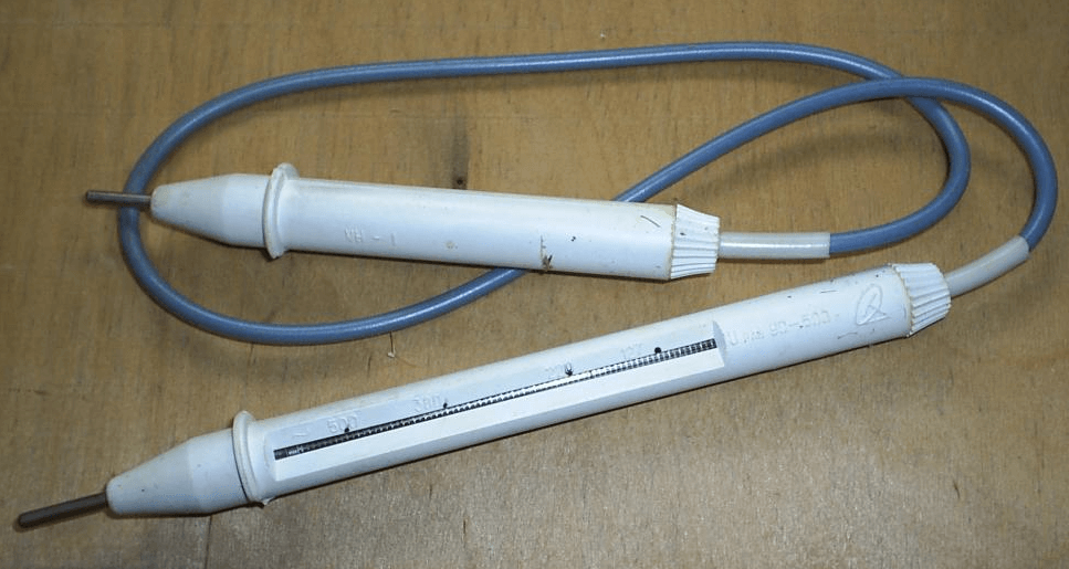
This device uses a special linear gas-discharge lamp and a scale on the body with a graduation of 127, 220, 380, 500 volts.
There are also universal voltage indicators for checking the presence of voltage and indicating its value from 12 to 380 V. For operation in DC circuits, up to 500 volts and alternating current, up to 380 volts. They can be additionally used to test the integrity of the connections.

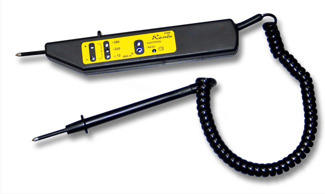
In these devices, LEDs are used as light indicators, and a large-capacity capacitor is used as a power source.
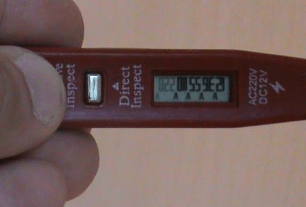
The digital voltage indicator has an LCD screen with printed volt values. At the maximum value of 220 volts, all values from the minimum to the maximum are illuminated on the screen. Those. this tester shows an approximate value. The only plus of this model is the lack of a power source.
Non-contact indicators are designed to detect live conductors, including those hidden in walls or panels. The circuit of this device reacts to an alternating electromagnetic field, is equipped with light and sound indication. We talked more about these devices when we talked about.

Terms of use
Before using the voltage indicator, you must make sure that it is working properly. To do this, in a known working network, you need to check the indication of the device. Only after a positive result is it allowed to use it.
It is forbidden to use an incandescent lamp as an indicator due to its low reliability and high risk of injury. When searching for the phase, it is necessary to install the pointer probe on the conductor of interest, hold the device in the right hand, hide the left hand behind the back, touch the end contact with the thumb of the right hand. This is for a single pole indicator.
For a two-pole probe with an indicator, put on the conductor or terminal of interest, and the second probe on zero or an adjacent phase. As you can see, there is nothing complicated in working with these devices. Be aware of the dangers of working under voltage and observe personal safety precautions.
So we examined the types, purpose and rules for using the voltage indicator. We hope the information provided was informative and useful for you!
When working in electrical installations, it is important to monitor the condition of circuits and live parts. An initial check (for safety reasons) detects the presence or absence of voltage in the work area. For this, a voltage presence indicator is used, which is manually connected by the operator, that is, it is not a structural element of the electrical installation.
In what cases it is imperative to use a voltage indicator:
- before starting repair work in an electrical installation;
- before applying portable grounding;
- to determine the site where the accident occurred;
- to identify the conductive parts of the electrical installation, which should not have a dangerous potential.
Important: The safety, and even the life of an electrician, depends on the correct use of the voltage indicator!
We will consider the principle of operation of high voltage indicators, types and methods of their application.
Division by type

General principles of operation of UNN (low voltage indicators)
For the indicator to operate (regardless of its type), it is necessary to ensure the flow of electric current through the circuit of the device. At the same time, ensuring the safety of the operator comes first. The two-pole design eliminates the touch of open areas of the body to live parts. But the single-pole voltage indicator works only when the auxiliary electrode is touched with a finger. Accordingly, the design must necessarily include a current limiting system to a safe value. After lowering the current threshold, the device turns into a low voltage indicator, regardless of the real potential on live parts.

equipment requirements
To ensure safety and reliability of operation, such devices are necessarily certified. The requirements of the state standard occupy at least a page of text, let's highlight the main ones:
- the insulating shell of the device must withstand a voltage exceeding the measurement range;
- single-pole pointer is made in only one case, thus eliminating the need for two-handed operation;
- at one end of the indicator there is a probe for contact with the tested section of the circuit, at the opposite end there is a contact pad for touching the operator's finger;
- a two-pole voltage indicator should consist of two cases with the same security indicators, connected by a flexible insulated cable 1 meter long;
- the open section of the probe must not exceed the length set for the selected measuring range;
- the light and (or) sound indicator of the potential presence must be clearly distinguishable under any measurement conditions.

Safety standards are uniform for the entire territory of the Russian Federation. No entity, be it Moscow or any regional center, has the right to relax the requirements for the production or use of such equipment.
Let's consider the work of the main types of voltage indicators.
Two-pole design
A high voltage indicator with two measuring contacts works on the principle of detecting the passage of current in the circuit section. An internal circuit compares the potential difference between the measuring point and ground (or neutral). If the response threshold exceeds the set value, an indication is triggered.
The design can be different, depending on the purpose: only indication, search for breakdown, measuring the exact voltage value, setting the range (220 V, 380 V). As an example, the illustration shows an electrical diagram of a device that determines the presence of a phase in the measured section and an approximate voltage threshold.

There are no complex integral elements, therefore such a pointer is reliable and trouble-free in any operating conditions. If measurements are taken outdoors, in bright light - parallel to the light indicator (in this case, it is an LED element), a sound one is added.
By adding a voltage measuring module to the measuring circuit, we get a single-mode multimeter designed for safe high voltage measurement.

This is interesting: An ordinary multimeter can also be used as a high voltage indicator. However, it will take time to get ready (setting the appropriate measurement mode). And not everything is so smooth with safety: specialized devices undergo strict certification.
It is not difficult to use such a device: a passive contact on the connecting wire is applied to the ground (zero) bus of the electrical installation. Then the measuring contact must touch the measuring point of the potential.

Benefits:
- high measurement accuracy, if necessary, you can expand the functionality;
- the ability to work with high voltage without additional protective equipment for the operator;
- operator protection is provided: there is no direct contact with open areas of the body.
Disadvantages:
- higher cost;
- the meter is rather bulky.
Single pole design
An electric current flows between the phase (measuring point) and the ground loop, which provides the human body (operator). The inside of the device is a simple electrical circuit consisting of a neon lamp and a resistor. The resistance is selected in such a way that the electric current does not exceed a value that is safe for humans.
At the same time, the current strength must ensure reliable operation of the indicator. For a neon lamp, a few hundredths of a milliampere is sufficient, so that the circuit works stably.

How do you use such a pointer? The device is held in one hand, the finger is placed on the back contact. Then the measuring probe is applied to the live part of the electrical installation. In the presence of potential, the control lamp lights up.
Interestingly, the various "advanced" transistor and LED circuits are not as reliable as a simple neon lamp and graphite resistor. A high percentage of false alarms does not allow the use of such a device for professional purposes.

Benefits:
- low cost of the device;
- efficiency of use;
- the ability to work with one hand.
Disadvantages:
- low accuracy and reliability;
- no advanced functionality;
- potentially dangerous: there is contact of open areas of the body with the measuring part of the device.
Non-contact voltage indicator
With direct access to the open contacts of an electrical wiring or electrical installation, it is easy to measure voltage. And how to determine the potential (at least its presence) in a hidden wiring?
For this, there are non-contact indicators (not to be confused with a clamp meter).

Such pointers do not work directly with an electric current, but with an electromagnetic field that occurs around the conductor. In fact, it is a coreless transformer, or inductor.
The simplest pointers react to an alternating magnetic field. When it is detected, a circuit assembled on triggers is triggered, and voltage is applied to the indicator (LED element). To enhance the detection effect, an audio signal is switched in parallel.
Of course, there can be no question of any voltage measurements. Moreover, the presence of an electromagnetic field depends on many factors, including the presence of a grounding bus near the conductor. In other words, a high-quality (according to the requirements of the PUE) laid electrical cable will not be detected by a contactless probe.
Important: You cannot use such a pointer as a hidden wiring detector, the detection distance is 1-2 cm in open air.
Benefits:
- ease of use: no need to look for open contacts;
- safety: no contact with live parts.
Disadvantages:
- in reality, the device does not even guarantee 50% of the result.
Based on the principle of operation of such a pointer, the stronger the current in the cable, the higher the probability of detecting the potential. Accordingly, if the appliance is not turned on, its supply cable will not actively form an electromagnetic field around itself. In this case, the potential on the phase wire is present, and the risk of electric shock remains.
Important: If you plan to use such a pointer, anyway, before starting work, you should check the absence of voltage in open areas with a conventional contact device.
Before using any measuring device, make sure you have the Safety Compliance Certification.
Related Videos
Dear readers, I welcome you to my resource "Notes of an Electrician".
Today we will talk with you about a high voltage indicator, or in abbreviated form it is called UVN.
I am writing this article, so to speak, in hot pursuit.
A few days ago, phasing was carried out for electrical equipment with a voltage class from 0.4 (kV) to 10 (kV).
UHN application
High voltage indicators (HVD) are used to check the presence or absence of high voltage in the switchgear on those. And also the UVV is used to check the phase coincidence, i.e. phasing high voltage.
What is a high voltage indicator made of?
To learn how to use a high voltage indicator correctly, you need to know its design.
This is what we are going to talk about now.
In my work and practice, most often it is necessary to use a high voltage indicator of the UVN-10 and UVNU-10 types. Therefore, in this article, I will focus on the design, testing and application of voltage indicators UVN-10 and UVNU-10.
High voltage indicator UVN-10 and UVNU-10 consists of the following main parts:
- working part
- indicator part (gas-discharge or LED lamp, slot-window for lamp or shade)
- insulating part
- handle with stop ring

The working and indicator parts are attached to the insulating part by means of a thread. The photo above shows the UVNU-10 transport type.
To bring it into working form, it is necessary to unscrew the thread, turn over the working and indicator parts and tighten the opposite. What will come of this - see the picture below.

The working part consists of elements that react to the presence of voltage in the controlled circuit. The body of the working part is made of an electrically insulating material with improved dielectric properties.
Pointers can be:
- contact type (UVN-10)
- contactless type
- combined type (UVNU-10)
In the first case, in the working part of the UVN there is a tip electrode (probe) for direct contact with the current-carrying part. In the second case, there is no tip electrode.
The indicator part of high voltage indicators consists of elements of light or light and sound indication.
Light indication is performed using:
- gas discharge lamps
- LED lamps (newer UVNU-10 designs)
The insulating part of voltage indicators above 1000 (V) is made of electrical insulating material that repels moisture, with improved dielectric and mechanical properties. Its surface should be smooth.
The insulating part of high voltage gauges should be free of various cracks, scratches, delamination and other defects.
It is forbidden to use paper-bakelite tubes as an insulating part.
The UVN handle can be part of the insulating part, or it can be a separate link. It all depends on the type and design of the voltage indicator used.
There are standards for the minimum length of handles and insulating parts of high voltage indicators, depending on the voltage class. All data are shown in the table below.

And yet, I forgot to mention that the voltage of the UVV indication should be no more than 25% of the nominal mains voltage.
All UVN during operation must periodically pass. The insulating part is subject to overvoltage tests, and the indication voltage is also checked.
The working part of the UVN is tested only at the request of the operating manual.
If, by the nature of work with the UVV, the working part can cause a phase to earth or two phases to close to each other, then in this case it is necessary to conduct electrical tests of the working part of the UVV.


Voltage indicators (UVV) react to capacitive current. When a high voltage indicator is introduced into the electric field, which is created from live parts that are energized, the capacitive current passes through the UHV along the circuit: live part - probe - gas discharge lamp (LED lamp) - capacitor built into the tube - conductivity of the insulating part - conductivity man - the earth.

P.S. This concludes the article on the high voltage pointer. I think that this material will be useful to you, tk. I repeat again and again that above all, and even more so in high voltage electrical installations.