A generator is a self-oscillating system that generates pulses of electric current, in which a transistor plays the role of a switching element. Initially, from the moment of its invention, the transistor was positioned as an amplifying element. The presentation of the first transistor took place in 1947. The presentation of the field-effect transistor took place somewhat later - in 1953. In pulse generators, it plays the role of a switch, and only in alternators does it realize its amplifying properties, while simultaneously participating in the creation of a positive feedback to support the oscillatory process.
A clear illustration of division frequency range
Classification
Transistor generators have several classifications:
- by the frequency range of the output signal;
- by the type of output signal;
- according to the principle of action.
The frequency range is a subjective value, but the following division of the frequency range is accepted for standardization:
- from 30 Hz to 300 kHz - low frequency (LF);
- from 300 kHz to 3 MHz - middle frequency (MF);
- from 3 MHz to 300 MHz - high frequency (HF);
- above 300 MHz - ultra-high frequency (UHF).
This is the division of the frequency range in the field of radio waves. There is a sound frequency range (AF) - from 16 Hz to 22 kHz. Thus, in order to emphasize the frequency range of the generator, it is called, for example, an HF or LF generator. The frequencies of the audio range, in turn, are also subdivided into HF, MF and LF.
By the type of output signal, generators can be:
- sinusoidal - for generating sinusoidal signals;
- functional - for self-oscillation of signals of a special form. A special case is a rectangular pulse generator;
- noise generators - generators of a wide spectrum of frequencies, in which, in a given frequency range, the signal spectrum is uniform from the bottom to the top frequency response.
By the principle of operation of generators:
- RC generators;
- LC generators;
- Blocking generators are short pulse shapers.
Due to fundamental limitations, usually RC oscillators are used in the low and audio range, and LC oscillators in the high frequency range.
Generator circuitry
RC and LC sinusoidal generators
The simplest implementation is a transistor generator in a capacitive three-point circuit - the Kolpitz generator (Fig. Below).

Transistor generator circuit (Colpitz generator)
In the Kolpitz scheme, elements (C1), (C2), (L) are frequency setting. The rest of the elements are a standard transistor strapping to ensure the required DC operation. The same simple circuitry is possessed by a generator assembled according to the inductive three-point scheme - the Hartley generator (Fig. Below).

Three-point generator circuit with inductive coupling (Hartley generator)
In this circuit, the generator frequency is determined by a parallel circuit that includes elements (C), (La), (Lb). A capacitor (C) is required to provide a positive AC feedback.
The practical implementation of such a generator is more difficult, since it requires a tapped inductance.
Both auto-oscillators are mainly used in the MF and HF ranges as carrier frequency generators, in frequency-setting local oscillator circuits, and so on. Regenerators for radio receivers are also based on oscillators. The specified application requires high frequency stability, therefore, the circuit is almost always supplemented with a quartz oscillation resonator.
The master current generator based on a quartz resonator has self-oscillation with a very high accuracy of setting the value of the frequency of the RF generator. Billions of a percent are far from the limit. Regenerators of radio stations use only quartz frequency stabilization.
The operation of generators in the area of low-frequency current and audio frequency is associated with the difficulties of realizing high inductance values. To be more precise, in the dimensions of the required inductor.
The Pierce generator circuit is a modification of the Colpitz circuit, implemented without the use of inductance (Figure below).

Pierce generator circuit without the use of inductance
In the Pierce circuit, the inductance is replaced by a quartz resonator, which eliminated the laborious and cumbersome inductor and, at the same time, limited the upper oscillation range.
The capacitor (C3) does not pass the DC component of the base bias of the transistor to the crystal resonator. Such a generator can generate vibrations up to 25 MHz, including the sound frequency.
The operation of all of the above generators is based on the resonant properties of an oscillatory system composed of capacitance and inductance. Accordingly, the vibration frequency is determined by the ratings of these elements.
RC current generators use the principle of phase shift in a resistive-capacitive circuit. The most commonly used scheme is with a phase-shifting chain (Fig. Below).

RC oscillator circuit with a phase-shifting circuit
Elements (R1), (R2), (C1), (C2), (C3) shift the phase to obtain the positive feedback necessary for the occurrence of self-oscillations. Generation occurs at frequencies for which the phase shift is optimal (180 degrees). The phase-shifting circuit introduces a strong signal attenuation, therefore such a circuit has increased requirements for the gain of the transistor. The circuit with the Wien bridge is less demanding on the parameters of the transistor (Fig. Below).

Wien Bridge RC Oscillator Circuit
The Wien double T-bridge is composed of elements (C1), (C2), (R3) and (R1), (R2), (C3) and is a notch filter tuned to the oscillation frequency. For all other frequencies, the transistor is engulfed in deep negative coupling.
Functional current generators
Functional generators are designed to form a sequence of pulses of a certain shape (the shape is described by a certain function - hence the name). The most common generators are rectangular (if the ratio of the pulse duration to the oscillation period is ½, then such a sequence is called "meander"), triangular and sawtooth pulses. The simplest rectangular pulse generator - a multivibrator, is served as the first circuit for beginner radio amateurs to assemble with their own hands (Fig. Below).

Multivibrator circuit - rectangular pulse generator
A feature of the multivibrator is that almost any transistor can be used in it. The duration of the pulses and pauses between them is determined by the ratings of the capacitors and resistors in the base circuits of the transistors (Rb1), Cb1) and (Rb2), (Cb2).
The self-oscillation frequency of the current can vary from units of hertz to tens of kilohertz. HF self-oscillations cannot be realized on a multivibrator.
Generators of triangular (sawtooth) pulses, as a rule, are built on the basis of generators of rectangular pulses (master oscillator) by adding a correction chain (Fig. Below).

Triangular pulse generator circuit
The shape of the pulses, close to triangular, is determined by the charge-discharge voltage on the plates of the capacitor C.
Blocking generator
The purpose of blocking generators is to generate powerful current pulses with steep edges and low duty cycle. The duration of the pauses between pulses is much longer than the duration of the pulses themselves. Blocking generators are used in pulse shapers and comparison devices, but the main field of application is a line scan master in information display devices based on cathode-ray tubes. Also blocking generators are successfully used in power conversion devices.
Field effect transistor generators
A feature of field-effect transistors is a very high input resistance, the order of which is commensurate with the resistance of electronic tubes. The circuitry solutions listed above are universal, they are just adapted for use. different types active elements. The Kolpitz, Hartley and others generators, made on a field-effect transistor, differ only in the denominations of the elements.
Frequency setting circuits have the same ratios. To generate HF oscillations, a simple generator made on a field-effect transistor according to the inductive three-point circuit is somewhat preferable. The fact is that the field-effect transistor, having a high input resistance, practically does not have a shunting effect on the inductance, and, therefore, the high-frequency generator will work more stable.
Noise generators
A feature of noise generators is the uniformity of the frequency response in a certain range, that is, the amplitude of oscillations of all frequencies included in a given range is the same. Noise generators are used in measuring equipment to assess the frequency characteristics of the tested path. Sound-range noise generators are often supplemented with a frequency response corrector in order to adapt to subjective loudness for human hearing. This noise is called “gray” noise.
Video
Until now, there are several areas in which the use of transistors is difficult. These are powerful generators of the microwave range in radar, and where it is required to receive particularly powerful high-frequency pulses. Powerful microwave transistors have not yet been developed. In all other areas, the vast majority of generators are performed exclusively with transistors. There are several reasons for this. First, the dimensions. Secondly, the power consumption. Third, reliability. On top of that, transistors, due to the peculiarities of their structure, are very easy to miniaturize.
Such a device will be very useful when testing the sound circuits of amplifiers for receivers, televisions and other industrial and home-made equipment. The diagram of the generator is based on the book by VG Borisov "Young radio amateur" (from 145-146 in the 8th edition), with minor changes.
AC generator circuit
The generator is assembled on the K155LA3 microcircuit (K555LA3 can be used), which consists of 4 2I-NOT elements. The generator itself is formed by the series-connected logic elements DD1.1, DD1.2, DD1.3, connected by inverters. Capacitor C1, with a capacity of 0.47 μF, creates a positive feedback between the DD1.2 output and the DD1.1 input. In principle, the signal can be removed from the DD1.3 output, the DD1.4 element simply inverts them. The pulse frequency can be changed by the variable resistor R1. Resistor R2 serves as an output level regulator. The resistance of the resistor R1 is 680 Ohm, R2 is 10 kOhm, variable resistors can be of any type. With the parameters of radio components specified in the diagram, the pulse frequency can be changed within 500 - 5000 Hz... The VD1 diode serves to protect against the supply of power to the wrong polarity; any low-power diode, for example, D220, is suitable as it. The circuit is mounted on a small breadboard. But due to the small number of parts, it is possible to carry out the scheme by surface mounting.
Generator assembly

The nominal supply voltage of the K155 and K555 microcircuits is 5 V, but the generator is operational when the circuit is powered by a 4.5 V "square" battery (battery type 3336 according to the old nomenclature), the voltage drop across the VD1 diode does not affect the device's performance. The device can be used to test the operation of audio amplifiers.
What is a sound generator and what is it eaten with? So let's first define the meaning of the word “generator”. Generator – from lat. generator- manufacturer. That is, explaining in home language, a generator is a device that produces something. Well, what is sound? Sound Are vibrations that our ear can discern. Someone kicked, someone hiccupped, someone sent someone - all these are sound waves that our ear hears. A normal person can hear vibrations in the frequency range from 16 Hz to 20 Kilohertz. Sound up to 16 Hertz is called infrasound, and the sound is more than 20,000 Hertz - ultrasound.
From all of the above, we can conclude that a sound generator is a device that emits some kind of sound. Everything is elementary and simple ;-) Why don't we collect it? Scheme in the studio!
As we can see, my diagram consists of:
- capacitor with a capacity of 47 nanoFarads
- resistor 20 Kilo-ohm
- transistors KT315G and KT361G, it is possible with other letters or generally some other low-power
- small dynamic head
- a button, but you can do it without it.
On a breadboard it looks something like this:
.JPG)
And here are the transistors:
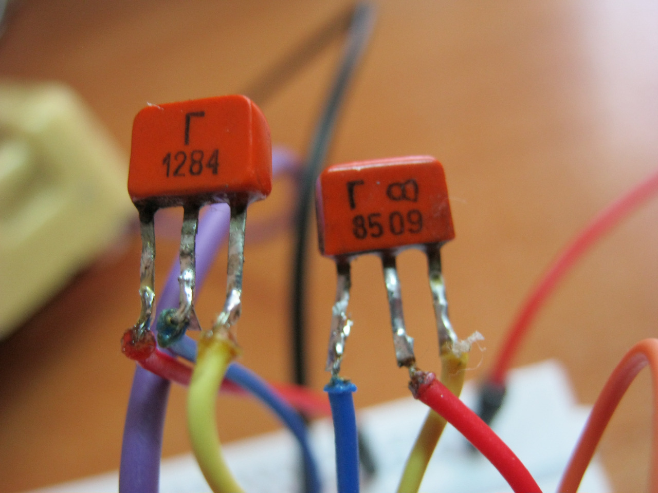
Left - KT361G, right - KT315G. For KT361, the letter is in the middle on the case, and for 315 it is on the left.
These transistors are complementary pairs to each other.
And here is the video:
The frequency of the sound can be changed by changing the value of the resistor or capacitor. Also, the frequency increases if the supply voltage is increased. At 1.5 Volts, the frequency will be lower than at 5 Volts. I have 5 volts on the video.
Do you know what else is funny? Girls have a much wider range of sound waves than boys. For example, guys can hear up to 20 Kilohertz, and girls can even hear up to 22 Kilohertz. This sound is so squeaky that it is very nerve-racking. What do I want to say by this?)) Yes, yes, why don't we choose such values of the resistor or capacitor so that the girls hear this sound, and the guys do not? Think about it, you are sitting in pairs, turn on your organ and look at the disgruntled faces of classmates (classmates). In order to tune the device, we certainly need a girl who could help us hear this sound. Not all girls perceive this high frequency sound as well. But the very, very funny is that it is impossible to find out where the sound is coming from))). Only if anything, I didn’t tell you that).
Sound frequency generator circuit operation description |

Sound frequency generator transistor circuit
Two transistors - field-effect VT1 and bipolar VT2 - are connected according to the scheme of a composite repeater having a small gain and repeating the phase of the input signal at the output. Deep negative feedback (OOS) through resistors R7, R8 stabilizes both the gain and the mode of the transistors.
But for the appearance of generation, a positive feedback is also needed from the output of the amplifier to its input. It is carried out through the so-called Wien bridge - a chain of resistors and capacitors R1 ... R4, C1 ... C6. The Wien bridge weakens both low (due to the increasing capacitance of capacitors C4 ... C6) and high (due to the shunting action of capacitors C1 ... C3). At the central frequency, those settings, approximately equal to 1 / 271RC, its gain is maximum, and the phase shift is zero. Generation occurs at this frequency.
By changing the resistance of the resistors and the capacitance of the bridge capacitors, the generation frequency can be changed over a wide range. For ease of use, a tenfold frequency range is selected with a double variable resistor R2, R4, and the frequency ranges are switched (Sla, Sib) by capacitors C1 ... C6.
To cover all audio frequencies from 25 Hz to 25 kHz three ranges are enough, but if you wish, you can add a fourth, up to 250 kHz (this is done by the author). By choosing a few large capacitances of capacitors or resistances of resistors, you can shift the frequency range down, making it, for example, from 20 Hz to 200 kHz.
The next important point in the design of a sound generator is the stabilization of the output voltage amplitude. For simplicity, the most ancient and reliable way stabilization - using an incandescent lamp. The fact is that the resistance of the lamp filament increases by a factor of almost 10 when the temperature changes from a cold state to full incandescence! A small indicator lamp VL1 with a cold resistance of about 100 ohms is included in the OOS circuit. It shunts the resistor R6, while the OOS is small, the PIC prevails and generation occurs. As the oscillation amplitude increases, the lamp filament heats up, its resistance increases, and the OOS increases, compensating for the PIC and thereby limiting the growth of the amplitude.
A step divider is turned on at the generator output voltage across resistors R10 ... R15, allowing to obtain a calibrated signal with an amplitude of 1 mV to 1 V... The divider resistors are wired directly to the pins of a standard 5-pin audio jack. The generator receives power from any source (rectifier, accumulator, battery), often from the same source from which the device under test is powered. The supply voltage across the transistors of the generator is stabilized by the R11, VD1 chain. It makes sense to replace resistor R11 with the same incandescent lamp as VL1 (indicator telephone, in "pencil" version) - this will expand the limits of possible supply voltages. Consumption current - no more 15 ... 20 mA.
Parts of almost any type can be used in the generator, but special attention should be paid to the quality of the double variable resistor R2, R4. The author used a rather large precision resistor from some outdated equipment, but double resistors from the volume or tone controls of stereo amplifiers are also suitable. Zener diode VD1 - any low-power, for stabilization voltage 6.8 ... 9 V.
When adjusting, one should pay attention to the smoothness of the generation of the approximately in the middle position of the engine of the tuning resistor R8. If its resistance is too low, the generation may stop in some positions of the frequency setting knob, and if it is too large, there may be a distortion of the sinusoidal waveform - limitation. You should also measure the voltage at the collector of the transistor VT2, it should be equal to about half the voltage of the stabilized power supply. If necessary, select the resistor R6 and, in extreme cases, the type and instance of the YT1 transistor. In some cases, the inclusion of an electrolytic capacitor in series with the incandescent lamp VL1 with a capacity of at least 100 uF("Plus" to the source of the transistor). In conclusion, the resistor R10 sets the signal amplitude at the output 1 in and calibrate the frequency scale using a digital frequency meter. It is common for all ranges.
A feature of this sound generator circuit is that everything in it is built on an ATtiny861 microcontroller and an SD memory card. The Tiny861 microcontroller consists of two PWM generators and, thanks to this, is able to generate high-quality sound, and in addition, it is able to control the generator with external signals. This audio frequency generator can be used to test the sound of high quality speakers or in simple amateur radio DIY such as an electronic bell.
Sound frequency generator circuit on the timer |
The audio frequency generator is built on the popular KP1006VI1 timer microcircuit (almost according to the standard scheme. The output signal frequency is about 1000 Hz. It can be adjusted in a wide range by adjusting the ratings of the C2 and R2 radio components. The output frequency in this design is calculated by the formula:
F = 1.44 / (R 1 + 2 × R 2) × C 2
The output of the microcircuit is not capable of providing high power, therefore a power amplifier is made on the field-effect transistor.

Chip and field key audio frequency generator
Oxide capacitor C1 is designed to smooth out the ripple of the power supply. The SZ capacitance connected to the fifth output of the timer is used to protect the control voltage output from interference.
Any stabilized one with an output voltage of 9 to 15 volts and a current of 10 A will do.
The world around us is full of sounds. In the city, these are mainly sounds associated with the development of technology. Nature gives us more pleasant sensations - birdsong, the sound of the surf, the crackling of a campfire on a camping trip. Often, some of these sounds need to be reproduced artificially - to imitate, simply out of desire, or based on the needs of your technical modeling circle, or when staging a performance in a drama club. Consider the descriptions of several sound simulators.
Intermittent siren sound simulator |

Let's start with the simplest design, this is a simple siren sound simulator. There are single-tone sirens, emitting a sound of one tone, intermittent when the sound gradually rises or falls, and then interrupts or becomes monotone, and two-tone, in which the tone of the sound periodically changes abruptly.
On transistors VT1 and VT2, a generator is assembled according to the scheme of an asymmetrical multivibrator. The simplicity of the generator circuit is explained by the use of transistors of different structures, which made it possible to do without many of the details necessary for the construction of a multivibrator on transistors of the same structure.

Siren sound simulator - circuit on two transistors
Oscillations of the generator, and hence the sound in the dynamic head, appear due to the positive feedback between the collector of the transistor VT2 and the base of VT1 through the capacitor C2. The tonality of the sound depends on the capacity of this capacitor.
When the SA1 switch applies the supply voltage to the sound generator, the head will not yet exist, since there is no bias voltage at the base of the VT1 transistor. The multivibrator is in standby mode.
As soon as the SB1 button is pressed, the capacitor C1 begins to charge (through the resistor R1). The bias voltage at the base of the transistor VT1 begins to increase, and at a certain value, the transistor opens. The sound of the desired key is heard in the dynamic head. But the bias voltage increases and the tone smoothly changes until the capacitor is fully charged. The duration of this process is 3 ... 5 s and depends on the capacitance of the capacitor and the resistance of the resistor R1.
It is worth releasing the button - and the capacitor will begin to discharge through the resistors R2, R3 and the emitter junction of the transistor VT1. The tone of the sound changes smoothly, and at a certain bias voltage at the base of the transistor VT1, the sound disappears. The multivibrator returns to standby mode. The duration of the capacitor discharge depends on its capacity, the resistance of the resistors R2, R3 and the emitter junction of the transistor. It is selected such that, as in the first case, the tonality of the sound changes within 3 ... 5 s.
In addition to those indicated in the diagram, other low-power silicon transistors of the corresponding structure with a static current transfer coefficient of at least 50 can be used in the simulator. large static transmission ratio. Capacitor C1 - K50-6, C2 - MBM, resistors - MLT-0.25 or MLT-0.125. Dynamic head - with a power of 0, G ... 1 W with a voice coil with a resistance of 6 ... 10 Ohm (for example, head 0.25GD-19, 0.5GD-37, 1GD-39). Power source - battery "Krona" or two series-connected batteries 3336. Power switch and button - of any design.
In standby mode, the simulator consumes a small current - it depends mainly on the reverse current of the transistor collector. Therefore, the contacts of the switch can be closed for a long time, which is necessary, say, when using the simulator as an apartment bell. When the contacts of the SB1 button are closed, the current consumption rises to about 40 mA.
Looking at the circuit of this simulator, it is easy to notice the already familiar node - a generator assembled on transistors VT3 and VT4. The previous simulator was assembled according to this scheme. Only in this case, the multivibrator does not work in standby mode, but in normal mode. For this, the bias voltage from the divider R6R7 is applied to the base of the first transistor (VT3). Note that transistors VT3 and VT4 have swapped places compared to the previous circuit due to a change in the polarity of the supply voltage.
So, a tone generator is assembled on transistors VT3 and VT4, which sets the first tone of the sound. On the transistors VT1 and VT2, a symmetrical multivibrator is made, thanks to which a second tone of sound will be obtained.
It happens like this. During operation of the multivibrator, the voltage on the collector of the transistor VT2 is either present (when the transistor is closed), or disappears almost completely (when the transistor is opened). The duration of each state is the same - about 2 s (i.e., the pulse repetition rate of the multivibrator is 0.5 Hz). Depending on the state of the transistor VT2, the resistor R5 shunts either the resistor R6 (through the resistor R4 connected in series with the resistor R5) or R7 (through the collector-emitter section of the transistor VT2). The bias voltage at the base of the VT3 transistor changes abruptly, so the sound of one or the other tonality is heard from the dynamic head.
What is the role of capacitors C2, SZ? They allow you to get rid of the influence of the tone generator on the multivibrator. If they are absent, the sound will be somewhat distorted. Capacitors are included in anti-series because the polarity of the signal between the collectors of transistors VT1 and VT2 changes periodically. A conventional oxide capacitor under such conditions works worse than the so-called non-polar one, for which the polarity of the voltage at the terminals does not matter. When two polar oxide capacitors are switched on in this way, an analog of a non-polar capacitor is formed. True, the total capacitance of the capacitor becomes half that of each of them (of course, with the same capacitance).

Siren sound simulator on four transistors
This simulator can use the same types of parts as in the previous one, including the power supply. For supplying the supply voltage, either a conventional switch with a latching position is suitable, as well as a push-button switch, if the simulator will work as an apartment bell.
Some of the parts are mounted on a printed circuit board (Fig. 29) made of one-sided foil-clad fiberglass. Mounting can be hinged, performed in the usual way - using mounting racks for soldering the leads of parts. The board is placed in a suitable housing in which the dynamic head and power supply are installed. The switch is placed on the front wall of the case or attached near the entrance door (if there is already a bell button there, its terminals are connected by conductors in isolation with the corresponding circuits of the simulator).
As a rule, the simulator, mounted without errors, starts working immediately. But if necessary, it can be easily adjusted to obtain a more pleasant sound. So, the tonality of the sound can be somewhat lowered by increasing the capacitance of the capacitor C5 or increased by decreasing it. The range of the tone change depends on the resistance of the resistor R5. The duration of the sound of a particular key can be changed by selecting capacitors C1 or C4.
So you can say about the next sound simulator, if you listen to its sound. Indeed, the sounds emitted by the dynamic head are reminiscent of exhaust emissions typical of a car, tractor or diesel locomotive engine. If the models of these machines are equipped with the proposed simulator, they will immediately come to life.
According to the scheme, the engine simulator resembles a single-tone siren somewhat. But the dynamic head is connected to the collector circuit of the transistor VT2 through the output transformer T1, and the bias and feedback voltages are fed to the base of the transistor VT1 through the variable resistor R1. For direct current, it is connected with a variable resistor, and for the feedback formed by a capacitor, it is connected with a voltage divider (potentiometer). When you move the slider of the resistor, the frequency of the generator changes: when the slider is moved down the circuit, the frequency increases, and vice versa. Therefore, a variable resistor can be considered an accelerator that changes the speed of the "engine" shaft, and hence the frequency of sound emissions.

Engine sound simulator - two-transistor circuit
For the simulator, transistors KT306, KT312, KT315 (VT1) and KT208, KT209, KT361 (VT2) with any letter indices are suitable. Variable resistor - SP-I, SPO-0.5 or any other, possibly smaller in size, constant - MLT-0.25, capacitor - K50-6, K50-3 or other oxide, with a capacity of 15 or 20 μF for a nominal voltage not below 6 V. Output transformer and dynamic head - from any small-sized ("pocket") transistor receiver. One half is used as winding I primary winding... The power source is a 3336 battery or three 1.5 V cells connected in series.
Depending on where you will use the simulator, determine the dimensions of the board and case (if you intend to install the simulator not on the model).
If, when the simulator is turned on, it will work unstable or there is no sound at all, swap the terminals of the capacitor C1 - with a positive terminal to the collector of the transistor VT2. By selecting this capacitor, you can set the desired limits for changing the number of revolutions of the "engine".
Cap ... drip ... drip ... - sounds are heard from the street when it is raining or drops of melting snow fall from the roof in spring. These sounds have a calming effect on many people, and according to some, even help to fall asleep. Well, perhaps you will need such a simulator for the phonogram in your school drama club. It will take only a dozen parts to build a simulator.
A symmetrical multivibrator is made on the transistors, the loads of the arms of which are high-resistance dynamic heads BA1 and BA2 - from them sounds of "drops" are heard. The most pleasant "drop" rhythm is set with the variable resistor R2.

Drop sound simulator - two-transistor circuit
For a reliable "start" of the multivibrator at a relatively low supply voltage, it is desirable to use transistors (they can be of the MP39 - MP42 series) with the largest possible static current transfer coefficient. Dynamic heads should be 0.1 - 1 W with a 50 - 100 Ohm voice coil (for example, 0.1GD-9). If there is no such head, you can use DEM-4m capsules or similar ones with the indicated resistance. Capsules with higher impedance (for example, from TON-1 headphones) will not provide the required sound volume. The rest of the details can be of any type. The power source is a 3336 battery.
The parts of the simulator can be placed in any box and mounted on its front wall dynamic heads (or capsules), a variable resistor and a power switch.
When checking and adjusting the simulator, you can change its sound by selecting a wide range of constant resistors and capacitors. If in this case a significant increase in the resistances of the resistors R1 and R3 is required, it is advisable to install a variable resistor with a large resistance - 2.2; 3.3; 4.7 kOhm to provide a relatively wide range of droplet frequency regulation.
Bouncing ball sound simulator circuit |
Want to hear a steel ball bounce off a ball bearing on a steel or cast iron plate? Then assemble the simulator according to the diagram shown in fig. 32. This is a variant of an asymmetrical multivibrator used, for example, in a siren. But unlike the siren, the proposed multivibrator does not have circuits for adjusting the pulse repetition rate. How does the simulator work? It is necessary to press (briefly) the SB1 button - and the capacitor C1 will be charged to the voltage of the power source. After releasing the button, the capacitor will become the source of power to the multivibrator. While the voltage on it is high, the volume of the “beats” of the “ball” reproduced by the dynamic head BA1 is significant, and the pauses are relatively long.


Bouncing Ball Sound Simulator - Transistor Circuits
Gradually, as the capacitor C1 is discharged, the nature of the sound will also change - the volume of the "beats" will begin to decrease, and the pauses will decrease. In conclusion, a characteristic metallic bounce will be heard, after which the sound will stop (when the voltage across the capacitor C1 falls below the transistor opening threshold).
Transistor VT1 can be any of the MP21, MP25, MP26 series, and VT2 - any of the KT301, KT312, KT315 series. Capacitor C1 - K.50-6, C2 - MBM. The dynamic head is 1GD-4, but another one will do, with good mobility of the diffuser and its possibly larger area. The power source is two 3336 batteries or six cells 343, 373 connected in series.
Parts can be mounted inside the simulator body by soldering their leads to the button and dynamic head leads. Batteries or cells are attached to the bottom or sides of the case with a metal bracket.
When adjusting the simulator, the most characteristic sound is achieved. To do this, select a capacitor C1 (it determines the total duration of the sound) in the range of 100 ... 200 μF or C2 (the duration of the pauses between "blows" depends on it) within 0.1 ... 0.5 μF. Sometimes for the same purposes it is useful to choose a transistor VT1 - after all, the work of the simulator depends on its initial (reverse) collector current and the static current transfer coefficient.
The simulator can be used as an apartment bell by increasing the volume of its sound. The easiest way to do this is to add two capacitors to the device - СЗ and С4 (fig. 33). The first of them directly increase the volume of the sound, and the second get rid of the sometimes occurring tone drop effect. However, with such a refinement, the "metallic" tint characteristic of a real bouncing ball is not always preserved.
Transistor VT3 can be any of the GT402 series, resistor R1 - MLT-0.25 with a resistance of 22 ... 36 ohms. In place of VT3, transistors of the MP20, MP21, MP25, MP26, MP39 - MP42 series can operate, but the sound volume will be somewhat weaker, although much higher than in the original simulator.
Surf sound simulator circuit |
By connecting a small set-top box to the amplifier of a radio, tape recorder or TV, you can get sounds that resemble the noise of the sea surf.
A diagram of such a simulator attachment is shown in Fig. 35. It consists of several units, but the main one is the noise generator. It is based on a silicon Zener diode VD1. The fact is that when applied to a zener diode through a ballast resistor with high resistance constant voltage exceeding the stabilization voltage, the Zener diode begins to "break through" - its resistance drops sharply. But due to the insignificant current flowing through the zener diode, such a "breakdown" does no harm to it. At the same time, the zener diode, as it were, goes into the noise generation mode, the so-called "shot effect" of its pn junction appears, and a chaotic signal consisting of random oscillations whose frequencies can be observed at the zener diode outputs (of course, using a sensitive oscilloscope) lie in a wide range.
It is in this mode that the zener diode of the console works. The ballast resistor mentioned above is R1. Capacitor C1, together with a ballast resistor and a zener diode, provides a signal of a certain frequency band, similar to the sound of surf noise.

Sea surf sound simulator circuit on two transistors
Of course, the amplitude of the noise signal is too small to be fed directly to the amplifier of the radio device. Therefore, the signal is amplified in a cascade on the transistor VT1, and from its load (resistor R2) is fed to the emitter follower, made on the transistor VT2, it allows you to eliminate the influence of the subsequent stages of the attachment on the operation of the noise generator.
From the load of the emitter follower (resistor R3), the signal is fed to a stage with a variable gain, assembled on a transistor VT3. Such a cascade is needed in order to be able to change the amplitude of the noise signal supplied to the amplifier, and thereby simulate the rise or fall of the "surf" loudness.
To accomplish this task, a transistor VT4 is connected to the emitter circuit of the transistor VT3, to the base of which the signal from the control voltage generator is fed through the resistor R7 and the integrating chain R8C5 - a symmetrical multivibrator on transistors VT5, VT6. In this case, the resistance of the collector-emitter section of the transistor VT4 changes periodically, which causes a corresponding change in the gain of the stage on the transistor VT3. As a result, the noise signal at the output of the stage (across the resistor R6) will periodically rise and fall. This signal is fed through the capacitor C3 to the XS1 connector, which is connected during operation of the set-top box to the input of the amplifier used.
The duration of the pulses and the repetition rate of the multivibrator can be changed by resistors R10 and R11. Together with the resistor R8 and the capacitor C4, they determine the duration of the rise and fall of the control voltage supplied to the base of the transistor VT4.
All transistors can be the same, the KT315 series with the highest possible current transfer ratio. Resistors - MLT-0.25 (MLT-0.125 is also possible); capacitors Cl, C2 - К50-3; SZ, C5 - C7 - K.50-6; C4 - MBM. Capacitors of other types are suitable, but they must be designed for a rated voltage not lower than that indicated in the diagram.
Almost all parts are mounted on a circuit board (Fig. 36) made of foil-clad material. Place the board in a housing of suitable dimensions. The XS1 connector and the XT1, XT2 clamps are fixed on the side wall of the case.
The set-top box is powered from any DC source with a stabilized and adjustable output voltage (from 22 to 27 V).
As a rule, it is not required to set up a set-top box. It starts working immediately after power is applied. It is not difficult to check the operation of the set-top box with the help of high-impedance headphones TON-1, TON-2 or other similar ones included in the XS1 “Output” connector sockets.
The nature of the sound of the "surf" is changed (if necessary) by selecting the supply voltage, resistors R4, R6, as well as by shunting the XS1 connectors with a capacitor C7 with a capacity of 1000 ... 3000 pF.
And here is another such sound simulator, assembled according to a slightly different scheme. It has an audio amplifier and a power supply, so this simulator can be considered a complete design.
The noise generator itself is assembled on a VT1 transistor according to the so-called superregenerator circuit. It is not very easy to understand the operation of a super-regenerator, therefore we will not consider it. Understand only that this is a generator in which the excitation of oscillations occurs due to the positive feedback between the output and the input of the stage. In this case, this connection is carried out through a capacitive divider C5C4. In addition, the super-regenerator is excited not constantly, but by flashes, and the moment of the appearance of flares is random. As a result, a signal appears at the output of the generator, which is listened to as noise. This signal is often referred to as "white noise".

The surf sound simulator is a more complex version of the circuit.
The DC super-regenerator operation mode is set by resistors Rl, R2, R4. The choke L1 and the capacitor C6 do not affect the operating mode of the stage, but they protect the power supply circuits from the penetration of a noise signal into them.
The L2C7 contour defines the "white noise" frequency band and allows you to get the largest amplitude of the "noise" oscillations that are detected. Then they go through the low-pass filter R5C10 and the capacitor C9 to the amplifier stage, assembled on the transistor VT2. The supply voltage to this stage is not supplied directly from the GB1 source, but through the stage assembled on the VT3 transistor. This is an electronic key that periodically opens with pulses arriving at the base of the transistor from a multivibrator assembled on transistors VT4, VT5. During periods when the transistor VT4 is closed, VT3 opens, and the capacitor C12 is charged from the GB1 source through the collector-emitter section of the transistor VT3 and the trimmer resistor R9. This capacitor is a kind of battery that feeds the amplifier stage. As soon as the transistor VT4 opens, VT3 closes, the capacitor C12 is discharged through the trimmer R11 and the collector-emitter circuit of the transistor VT2.
As a result, on the collector of the transistor VT2 there will be a noise signal, modulated in amplitude, that is, periodically increasing and decreasing. The rise time depends on the capacitance of the capacitor C12 and the resistance of the resistor R9, and the decay depends on the capacity of the specified capacitor and the resistance of the resistor R11.
The modulated noise signal is fed through the capacitor JV to an audio frequency amplifier based on transistors VT6 - VT8. At the input of the amplifier there is a variable resistor R17 - a volume control. From its engine, the signal is fed to the first amplifier stage, assembled on a VT6 transistor. This is a voltage amplifier. From the load of the stage (resistor R18), the signal goes through the capacitor C16 to the output stage - a power amplifier made on transistors VT7, VT8. A load is included in the collector circuit of the transistor VT8 - the dynamic head BA1. The sound of "sea surf" is heard from it. Capacitor C17 attenuates the high-frequency, "whistling" components of the signal, which somewhat softens the timbre of the sound.
About the details of the simulator. Instead of the KT315V (VT1) transistor, you can use other transistors of the KT315 series or the GT311 transistor with any letter index. The rest of the transistors can be any of the MP39 - MP42 series, but with the greatest possible current transfer ratio. To obtain greater output power, the VT8 transistor is desirable to use the MP25, MP26 series.
Choke L1 can be ready-made, such as D-0.1 or another.
Inductance 30 ... 100 μH. If it is not there, you need to take a rod core with a diameter of 2.8 and a length of 12 mm from ferrite 400NN or 600NN and wind a turn on it to a turn of 15 ... 20 turns of the PEV-1 wire 0.2 ... 0.4. It is advisable to measure the resulting inductance of the choke on a reference device and, if necessary, select it within the required limits by decreasing or increasing the number of turns.
The L2 coil is wound on a frame with a diameter of 4 and a length of 12 ... 15 mm made of any insulating material with a PEV-1 wire 6.3 - 24 turns with a tap from the middle.
Fixed resistors - MLT-0.25 or MLT-0.125, tuning resistors - SPZ-16, variable - SPZ-Sv (it is with a SA1 litany switch). Oxide capacitors - К50-6; C17 - MBM; the rest are KM, K10-7 or other small-sized ones. The dynamic head - with a power of 0.1 - I W with the highest possible resistance of the voice coil (so that the transistor VT8 does not overheat). The power source is two 3336 batteries connected in series, but the best runtime results will be obtained with six 373 cells connected in the same way. Suitable, of course, is the power supply option from a low-power rectifier with a constant voltage of 6 ... 9 V.
The details of the simulator are mounted on a board (Fig. 38) made of foil-coated material with a thickness of 1 ... 2 mm. The board is installed in a case, on the front wall of which a dynamic head is attached, and a power source is placed inside. The size of the case is largely dependent on the size of the power supply. If the simulator is used only to demonstrate the sound of the sea surf, the power source can be a Krona battery - then the dimensions of the case will sharply decrease, and the simulator can be mounted in a case from a small-sized transistor radio receiver.
Set up a simulator like this. Disconnect the resistor R8 from the capacitor C12 and connect it to the negative power wire. Having set the maximum sound volume, select the resistor R1 until the characteristic noise ("white noise") in the dynamic head is obtained. Then the connection of the resistor R8 with the capacitor C12 is restored and the sound in the dynamic head is listened to. By moving the trimmer slider R14, the most reliable and pleasing to the ear frequency of the "sea waves" is selected. Further, by moving the slider of the resistor R9, the duration of the rise of the "wave" is set, and by moving the slider of the resistor R11, the duration of its decay.
To get a high volume of the "sea surf", you need to connect the extreme terminals of the variable resistor R17 with the input of a powerful audio amplifier. The best experience can be obtained by using a stereo amplifier with outboard acoustic systems operating in monaural signal playback mode.
Rain noise sound simulator simple circuit |
If you want to listen to the beneficial effects of the measured noise of rain, forest or surf. These sounds are relaxing and soothing.

Rain noise sound simulator - circuit based on operational amplifier and counter
The rain noise generator is made on the TL062 microcircuit, which includes two operational amplifiers. Then the generated sound is amplified by transistor VT2 and fed to the SP speaker. For better matching of the HF sound spectrum, it is cut off by a capacitor C8, which is controlled by field-effect transistor VT1 works essentially as a variable resistance. Thus, we get automatic control of the tone of the simulator.
The CD4060 counter has a timer with three turn-off time delays: 15, 30 and 60 minutes. Transistor VT3 is used as a generator power switch. By changing the values of resistance R16 or capacitance C10, we get different time intervals in the operation of the timer. By changing the value of the resistor R9 from 47k to 150k, you can change the speaker volume.
